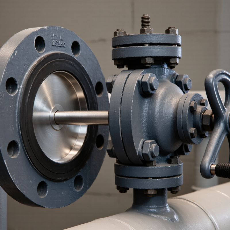
Choosing the right Cast Iron Butterfly Valve starts with the conditions it will actually face—not just the pipe size. A valve controlling cool water in a treatment line may need different materials and sealing performance from one handling abrasive process water. Pressure, temperature, flow direction, operating frequency, and fluid chemistry all matter. So does the connection style. A wafer valve fits between flanges; a lug-style valve can offer more flexibility during maintenance. Small details can change the decision.
As [verified valve-industry expert’s name] puts it, “[Insert a verified quotation about matching valve design to service conditions].” That principle is practical: check the pressure-temperature rating, disc and seat materials, shaft design, and actuator requirements against the system specifications. Look closely at the seat, too. A mismatch may show up later as leakage, stiff operation, or premature wear. Not every catalog description makes those limits clear.
This guide explains how to compare options and ask suppliers useful questions. It also points out where selection can be less certain. Service conditions may vary, and a valve that works well in one line may perform poorly in another. Treat the manufacturer’s data sheet as a starting point, then confirm critical details with a qualified valve engineer. A careful choice protects reliable flow. It can also prevent avoidable maintenance.
A cast iron butterfly valve uses a circular disc inside a cast iron body to open, restrict, or stop flow. The disc sits across the pipe and turns on a stem connected to a lever or actuator. A quarter-turn moves it from nearly closed to open. Simple motion. When open, the disc aligns with the flow, though it still creates some resistance. When closed, its edge presses against a seat to limit leakage.
The body supports the internal parts and connects to the pipeline, while the seat forms the sealing surface. Seat materials vary, so check their compatibility with the fluid, temperature, and operating conditions. Cast iron can suit many water and general-service systems, but pressure limits depend on the valve’s design and rating. Details matter. In the field, a stiff handle may point to debris, wear, or poor alignment; forcing it can damage the stem or seat. I would also check whether the valve is intended for isolation or regular throttling, since partially open operation can increase wear in some applications. A little uncertainty remains until the actual service conditions are known.
Before selecting a cast iron butterfly valve, record the fluid, normal and peak pressure, temperature range, flow rate, and required shutoff performance. Include startup, shutdown, and pump-trip conditions; brief pressure surges can matter as much as steady operation. Water is not one uniform service. Check for solids, treatment chemicals, abrasion, and corrosion, then confirm that the valve body, disc, and seat materials suit the fluid.
Sizing matters. A valve that is too large may operate mostly near closed, reducing control resolution; one that is too small can restrict flow. Note the pipe diameter, connection type, available space, and actuator needs. The U.S. Department of Energy’s Improving Pumping System Performance: A Sourcebook for Industry (2006) reports that pumping systems use nearly 20% of global electricity demand and 25–50% of energy in some industrial operations. That figure is system-wide, not a valve-efficiency estimate, but it underlines why pressure loss and operating range deserve attention.
Use the system’s design documents, then compare them with field readings where possible. A tidy spreadsheet can miss a real-world transient. Mark uncertain values for verification, and check the valve’s pressure-temperature ratings and installation limits against its technical documentation before specifying it.
This illustrative water-system example shows the operating, maximum steady, transient, and design pressures to establish before selecting a valve. These figures are example system inputs, not cast iron valve ratings. Confirm the valve’s pressure–temperature limits, surge suitability, and fluid compatibility against its technical data.
Choose valve size from measured flow, not pipe diameter alone. A valve matched only to the line can run near-closed, creating turbulence, noise, and poor control. Check normal, minimum, and peak flow, plus acceptable pressure loss. For example, a process line carrying mostly low flow may need a smaller effective opening. This is easy to overlook.
EPA’s 2023 Drinking Water Infrastructure Needs Survey and Assessment estimates $625 billion in U.S. drinking-water investment needs over 20 years. That scale makes dependable component selection important, though it does not prescribe a valve size.
Confirm the pressure rating against maximum operating pressure, temperature, and possible surges. The valve, seat, shaft, and mating flanges must all suit the service; the weakest component sets the practical limit. Use the applicable product standard and manufacturer’s pressure-temperature data, rather than assuming every cast-iron valve shares one rating. AWWA C504 covers rubber-seated butterfly valves for waterworks service. Verify its scope against the actual application.
Connection type affects installation and maintenance. Wafer valves fit between flanges and save space, but removal may require supporting or shifting nearby pipework. Lug-style bodies allow independent bolting on each side when the design permits; flanged ends can simplify alignment but need more room. Check flange drilling, face-to-face dimensions, bolt access, and flow direction before ordering. Site drawings can be imperfect, so confirm dimensions in the field before the crew lifts the valve into place.
Compare the valve body, disc, and seat against the fluid and operating conditions. Gray cast iron can suit many low-pressure water services, while ductile iron generally offers greater strength under mechanical stress. Neither material is automatically right for every installation. Check pressure, temperature, corrosion exposure, and any water-quality requirements. Small details matter. A damp outdoor pit, for example, may call for a protective coating and corrosion-resistant disc materials. Check the fluid. Elastomer seats such as EPDM or NBR differ in chemical compatibility and temperature limits, so confirm the manufacturer’s published data rather than relying on the material name alone.
Seat design affects sealing and maintenance. A resilient seat is common for tight shutoff, while other seat arrangements may better suit higher temperatures or frequent operation. Consider whether the valve is for isolation or throttling; continuous throttling can increase wear, depending on flow conditions.
Standards also need careful comparison. AWWA C504, API 609, and EN 593 cover different application contexts and requirements. They are not interchangeable labels. Verify the relevant edition, pressure class, dimensions, testing provisions, and project specification with the supplier or engineer. A catalogue rating is useful, but it does not replace checking the complete assembly against actual service conditions. One overlooked limitation: even a correctly specified valve can perform poorly if installed with unsuitable piping alignment or operating torque.
How to Choose the Right Cast Iron Butterfly Valve
Evaluate Installation, Operation, and Maintenance Requirements
Start with the actual piping conditions. Check the line size, pressure, temperature, and fluid, then compare them with the valve’s published limits. Cast iron can suit many water and utility systems, but it is not right for every service. Confirm the required connection style, face-to-face dimension, and flange rating before ordering. Small mismatches can turn a straightforward installation into rework.
Plan for access, too. The handle or actuator needs clear space to move through its full range, and nearby pipes should not block inspection. Align the valve carefully between flanges; uneven tightening can stress the body or affect sealing. Follow the specified bolt sequence and torque. Do not use the valve to correct poor pipe alignment. That shortcut may seem harmless, but it can create trouble later.
Think through operation and upkeep before the line is live. Check that the disc opens and closes without hitting pipe interiors, and confirm the actuator provides suitable operating torque. A short cycle test helps reveal binding. Keep the valve accessible for inspection, and establish a safe isolation plan before maintenance. Inspect for leakage, corrosion, and debris around the disc and seat. Maintenance needs vary with the fluid and cycle frequency, so a fixed schedule may need adjustment. That part is easy to overlook.
| Evaluation Dimension | What to Check | Selection Guidance | Installation, Operation, and Maintenance Implications |
|---|---|---|---|
| Service and Medium | Identify the fluid or gas, operating temperature, pressure, concentration, suspended solids, and any cleaning chemicals. | Confirm that the body, disc, shaft, seat, and fasteners are suitable for the complete service conditions. Do not assume cast iron is suitable for every corrosive or abrasive medium. | Check material compatibility before installation. Inspect wetted parts regularly if the medium can cause corrosion, erosion, or seat damage. |
| Pressure and Temperature | Record normal and maximum operating pressure, temperature, pressure surges, and differential pressure across the valve. | Use the valve’s published pressure–temperature limits and differential-pressure ratings. These vary by design, size, materials, and applicable standard. | Do not use a general pressure class as a substitute for the specific manufacturer’s rating. Consider water hammer and other pressure transients. |
| Valve Size and Flow | Verify pipe size, required flow, allowable pressure loss, and whether the valve will be used for isolation or throttling. | Select a size and flow characteristic appropriate to the system. A butterfly valve may be used for throttling only when its design and service conditions permit it. | Confirm that the disc can rotate through its full travel without contacting pipe linings, nearby fittings, or other obstructions. |
| Body and Connection Style | Check the required wafer or lug configuration, flange standard, face-to-face dimensions, and available installation space. | Match the valve to the piping and flange arrangement. A lug-style valve is suitable for end-of-line service only when the valve is specifically rated for that condition. | Confirm bolt size, length, and access before installation. Follow the valve instructions for flange alignment and tightening sequence. |
| Body Material | Determine whether cast iron is appropriate for the system’s mechanical loads, pressure, temperature, and installation environment. | Cast iron is rigid but comparatively brittle and can be damaged by impact, excessive piping stress, or mishandling. Consider ductile iron or another material if the service requires greater impact resistance. | Support and align piping independently as required. Avoid striking the valve body or using it to correct pipe misalignment. |
| Disc, Shaft, and Seat | Check disc and shaft materials, seat material, media compatibility, temperature range, and required leakage performance. | Select materials for the actual fluid and operating conditions. Resilient seats can provide tight shutoff, but their suitability depends on temperature, chemicals, and pressure. | Inspect the seat and disc for cuts, deposits, corrosion, or wear. Replace damaged parts according to the valve maintenance instructions. |
| Actuation and Control | Decide between a lever, gear operator, pneumatic actuator, or electric actuator; note operating frequency and control requirements. | Size the operator or actuator using the required torque for the valve size, differential pressure, seat, and service—not valve diameter alone. | Provide access for operation and maintenance. For powered actuation, verify the supply, control signals, fail position, and any required position indication. |
| Flow Direction and Shutoff | Check whether the valve must seal in one or both directions and whether it will face reverse pressure or dead-end service. | Verify the permitted flow direction and pressure differential for the specific valve. Do not presume bidirectional shutoff or dead-end suitability. | Install in the orientation specified by the manufacturer. Confirm that the selected seat and valve configuration meet the required isolation duty. |
| Installation and Clearance | Check pipeline alignment, flange condition, disc clearance, actuator orientation, and nearby elbows or fittings. | Use the installation instructions for the exact valve design. Confirm whether separate flange gaskets are required; some resilient-seated designs use an integral liner or seat as the sealing element. | Keep the disc slightly open during installation if instructed. Center the valve between flanges and tighten bolts evenly in a cross pattern to avoid uneven loading. |
| Operation and Cycling | Assess the expected number of operating cycles, speed of operation, and potential for pressure surges. | Choose an operator suited to the duty and avoid rapid closure where it could create damaging pressure transients. | Operate through the intended travel without forcing the lever or actuator against a mechanical stop. Investigate abnormal torque or vibration promptly. |
| Maintenance and Isolation | Consider inspection access, spare-part availability, maintenance intervals, and whether the line can be safely isolated. | Choose a design that can be inspected and serviced within the site’s safety and maintenance procedures. | Before inspection or service, isolate the line, relieve pressure, drain or vent the system as appropriate, and verify a safe condition. Check fasteners, external corrosion, seat condition, and actuator function. |
| Standards and Documentation | Confirm applicable piping, dimensional, testing, and material requirements for the project and jurisdiction. | Request documentation for dimensions, materials, pressure–temperature limits, testing, and installation requirements for the selected valve. | Keep the valve data and maintenance records accessible so that future replacement parts and operating limits can be verified. |

Selection note: Final suitability depends on the specific valve design and system conditions. Verify ratings, materials, installation details, and service limits against the valve documentation and applicable project requirements.