

Choosing a Relay Test Set is not a catalog exercise. It is a reliability decision made at a workbench, with trip curves, wiring diagrams, and commissioning deadlines in view. The International Energy Agency’s Electricity 2024 report projected global electricity demand growth averaging 3.4% annually from 2024 through 2026. More demand puts greater pressure on dependable grid equipment and protection practices. NERC’s 2024 State of Reliability also tracks protection-system misoperations as a measurable reliability concern. These reports do not rank test sets, but they show why accurate, repeatable relay testing matters.
J. Lewis Blackburn, co-author of Protective Relaying: Principles and Applications, is a respected technical reference in the field. I cannot verify a verbatim quotation from him here, so I will not invent one. His work’s practical emphasis can be paraphrased this way: protection depends on sound application and testing. That distinction matters. A set that looks capable on a specification sheet may still be awkward for your relay types, test plans, or field conditions.
Check current range, output accuracy, binary inputs and outputs, timing resolution, software workflow, and calibration support. Then consider the real job: Will the unit fit a crowded control room? Can technicians reproduce a test without rebuilding settings each time? Small details count. So does training. This guide compares the factors that help utilities, contractors, and commissioning teams choose a Relay Test Set suited to their protection tasks. Use the criteria as a starting point, not a substitute for reviewing manufacturer specifications and your own test procedures.
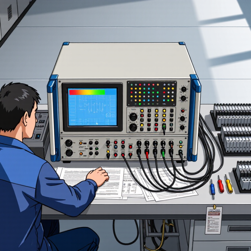
How to Choose the Right Relay Test Set?
Understanding the Purpose of a Relay Test Set
A relay test set supplies controlled electrical signals to check whether a protective relay responds as intended. It can simulate conditions such as overcurrent, undervoltage, or phase imbalance without creating an actual fault on the circuit. The test helps technicians examine pickup values, operating time, and the relay’s programmed logic. Small timing differences matter.
During commissioning, a technician may inject a measured current and compare the relay’s response with its settings. Later, the same checks can help identify drift, wiring mistakes, or configuration changes during maintenance. A useful test set should match the relay’s input types and the tests required by the site’s procedures. Clear measurement records also make results easier to review.
The test set does not verify the entire protection system by itself. Connections, trip circuits, and test settings still need careful attention. A passing result can be misleading if the wrong parameters were entered. That happens. For example, testing a relay with an outdated setting sheet may confirm its behavior, but not its suitability for the current installation. Operators should follow approved procedures, isolate equipment as required, and document both the setup and results.
A relay’s type determines what a test set must measure. Electromechanical relays use moving contacts and coils, so checks may include pickup voltage, dropout behavior, contact continuity, and operating time. Solid-state relays have no moving parts; their input thresholds, output behavior, and leakage current need different attention. Protection relays add another layer. They may require controlled current or voltage injection to verify settings, trip logic, and timing.
Match the test set’s outputs and measurement range to the relay’s nameplate and documentation. Check coil voltage, AC or DC supply, contact configuration, and expected current before connecting anything. For a protection relay, confirm whether the test requires single-phase or three-phase injection, and whether binary inputs and outputs are needed to observe trip signals. A set with the wrong range can produce misleading results. Details matter.
The test procedure should reflect the relay’s actual duty, not just its category. A door-control relay and a feeder protection relay may both be electromechanical, yet their test priorities differ. Keep the circuit isolated as required by the site procedure, and record settings, measured values, and ambient conditions. Labels can be incomplete, and field assumptions sometimes miss a wiring variant. Pause and verify the terminal diagram when readings seem inconsistent; a tidy test plan can still need revision.
How to Choose the Right Relay Test Set?
Comparing Test Set Capabilities and Performance
A relay test set should reproduce the signals your protection scheme actually sees. Compare current and voltage output accuracy, phase-angle control, timing resolution, and channel count. For a differential relay, for example, confirm the set can synchronize multiple current outputs and reproduce the phase relationships used in your test plan. For distance protection, check whether it can create repeatable voltage and current changes without manual workarounds. IEC 60255 series standards provide a useful framework for relay performance, but the relay manufacturer’s test requirements still matter. One specification sheet rarely tells the whole story.
The U.S. Department of Energy’s 2023 National Transmission Needs Study reports that roughly 70% of U.S. transmission lines are over 25 years old. Aging grid assets make dependable protection testing important, but that statistic does not indicate the condition of any individual relay. Compare test sets using documented accuracy, calibration traceability, and repeatability under realistic loads. Check how the software records settings and results; a fast test is less useful if another technician cannot reproduce it. A limitation worth admitting: bench performance may differ from field performance.
Tips: Verify output accuracy at the currents and voltages you actually use. Test a sample relay before purchase. Small details matter. Also check setup time, portability, and whether the interface remains clear when schedules get tight.
Compare the typical capabilities of common relay test set configurations. Values are indicative ranges, not specifications for a particular instrument; confirm output limits, accuracy, and test requirements in the relevant product documentation.
| Capability | Compact Single-Phase Set | Three-Phase Set | Six-Current Set | High-Current Set |
|---|---|---|---|---|
| Typical output configuration | 1 current channel and 1 voltage channel | 3 current channels and 3 or 4 voltage channels | 6 current channels and 4 voltage channels | 1 or more current channels designed for higher current injection |
| Typical current output range | Up to about 10–30 A on one channel | Often up to about 20–30 A per phase | Often up to about 20–30 A per channel; parallel operation may provide higher current | Commonly about 50–100 A or more on a dedicated output, depending on duty and load |
| Typical voltage output range | Often up to about 150–300 V AC | Often up to about 150–300 V AC per channel | Often up to about 150–300 V AC per channel | Varies by configuration; high-current capability is the primary design focus |
| Phase and timing capability | Single-phase tests; basic current and voltage timing tests | Three-phase magnitude, angle, frequency, and sequence tests | Independent multi-phase injection for complex protection schemes and end-to-end simulations | High-current pickup, trip, and primary-current-related testing where suitable |
| Typical accuracy class | Often around 0.1% of reading or better for selected ranges | Often around 0.1% of reading or better for selected ranges | Often around 0.1% of reading or better for selected ranges | Accuracy varies with current range, output burden, and test duration |
| Binary inputs and outputs | Usually includes basic trip-contact monitoring; output count may be limited | Typically supports trip contact monitoring and breaker or logic simulation | Often provides multiple inputs and outputs for sequencing and logic tests | May include trip timing inputs; check whether additional I/O is required |
| Portability and setup | Generally the lightest option; suited to routine field checks | Portable, with more connections and configuration than a single-phase set | Typically heavier and more involved to connect; offers broader test coverage | Often larger and heavier; may require careful duty-cycle and supply planning |
| Best suited to | Basic overcurrent, voltage, and single-phase relay checks | Most routine three-phase protection relay commissioning and maintenance | Differential, distance, multi-terminal, and other tests needing several independent currents | Applications requiring higher test current than a standard relay set can provide |
| Key selection check | Confirm the required current, voltage, and trip-contact test range | Check simultaneous output, phase-angle control, and protection test workflow | Verify independent channel control, output burden, and required binary I/O | Confirm maximum current at the intended load, permissible duration, and cooling requirements |
Note: Maximum outputs and accuracy depend on the connected load, selected range, ambient conditions, and permitted operating duration. Use the relay manufacturer’s test procedures and applicable electrical safety practices.
Evaluating Safety, Usability, and Connectivity
Safety should be easy to verify before a test begins. Check that the set’s output ratings match the relay and test plan. Look for clearly marked terminals, protected test leads, and visible status indicators. Grounding instructions and emergency shutdown controls should be easy to find, not buried in a menu. A sturdy case helps when equipment moves between sites. Still, no safety feature replaces a careful setup and trained operation.
Usability matters during long test sequences. A readable screen, logical menus, and simple test templates can reduce setup errors. Try common tasks, such as changing a current value or reviewing a trip time, before choosing a unit. Small details matter. A cramped keypad can slow work when gloves are on. Connectivity should fit the team’s actual workflow. USB or network options may support report transfer and integration with existing tools. Confirm file formats, software compatibility, and how test records are stored. More connection options are not always better; unused features can add complexity. It is worth checking how the set behaves when a connection drops. That takes practice. A short trial with a representative relay often reveals more than a feature list.
Choosing a relay test set starts with the work you actually perform, not the longest feature list. A compact unit may suit routine overcurrent checks, while differential or distance testing can require more channels and precise timing control. Compare its current and voltage outputs with the relay’s test requirements. Check accuracy, burden capacity, and whether the software supports your usual test sequences. A lower purchase price can become costly if setup takes longer or extra modules are needed. I still find this easy to overlook.
Tips: List your common tests. Check the cables. Confirm calibration support.
Field conditions matter just as much as specifications. If technicians carry equipment between substations, weigh the set with its leads and case, not just the main unit. For outdoor work, consider screen readability, connector protection, and operating temperature. A battery can help where outlets are scarce, but confirm expected runtime under realistic test loads. Dusty sites and cramped panels expose weak points quickly. I would also compare setup time using a familiar relay, then repeat the check with a less common model. That small trial may reveal confusing controls or missing adapters. Review calibration records, service options, and data-export needs before buying. A modest set can be the right choice, but only when its limits match the jobs ahead.
Compare typical equipment configurations against budget and field requirements.
The 1–5 scores are qualitative planning ratings, not measured product specifications. Higher scores indicate a stronger typical fit for each criterion. Actual cost, portability, and capabilities depend on the selected configuration and accessories; check requirements such as output channels, current and voltage ranges, and available power before purchasing.

