
What Is Injection Molding Tooling and How Does It Work?

Injection molding tooling is the system of molds, inserts, and supporting components that shapes molten plastic into repeatable parts. It is more than a hollow block of metal. A steel or aluminum mold contains cavities, cooling channels, vents, and moving sections that guide each molding cycle. These features influence part shape, surface finish, cycle time, and manufacturing cost. Small details matter. A vent that is too shallow may trap air; an uneven cooling layout can leave a part warped or slow to release. Those effects often become clear only after a tool is tested. That is easy to miss when a design looks complete on screen.

John Bozzelli, a recognized scientific-molding educator, is often associated with the principle, “The process is the product.” It captures an important point: tooling and process settings must work together. During a cycle, the mold closes, receives injected polymer, holds it under pressure, cools the material, and opens to release the part. The sequence sounds simple. The engineering is not. Resin choice, part geometry, gate location, and cooling design all affect how reliably the tool performs. This guide explains what injection molding tooling includes, how its main components function, and what designers and manufacturers consider when developing a mold. Some problems still emerge only during trials, so even a carefully reviewed tool may need adjustment. That is not failure; it is useful evidence for improving the next cycle.
What Is Injection Molding Tooling and How Does It Work?

What Injection Molding Tooling Is and What It Controls

Injection molding tooling is the engineered mold system that shapes molten plastic into repeatable parts. It includes the cavity, core, cooling channels, gates, ejectors, and alignment features. The tool controls the part’s geometry, surface finish, wall thickness, and dimensional stability.

The numbers show why tooling matters. PlasticsEurope reported global plastics production of about 400.3 million tonnes in 2022. Grand View Research also estimated steady growth in the global injection molding machine market through 2030. More production increases pressure on mold life and cycle consistency.

Cooling channels control how quickly heat leaves the part. Poor cooling can create warpage, sink marks, or uneven shrinkage. Gates control filling direction and pressure. Ejectors control removal without damaging edges or visible surfaces. Steel selection controls wear, polishing quality, and maintenance intervals.

Small details matter.

A cavity may look correct but still produce inconsistent parts. In practice, tooling design is rarely perfect on the first attempt. Engineers often adjust vent depth, cooling balance, or gate position after trial runs. That feedback is valuable, although it can expose weaknesses in the original design. Reliable tooling comes from measured testing, documented changes, and process knowledge rather than assumptions.

The Main Parts and Functions of an Injection Mold

Injection molding tooling is a precision system that shapes heated polymer inside a closed mold. Its performance depends on several coordinated parts. PlasticsEurope’s Plastics—the Fast Facts 2023 reported 400.3 million tonnes of global plastics production in 2022. Not all plastics are molded, but the figure shows the scale behind modern tooling demand.

The mold base supports the entire assembly and keeps both halves aligned. The cavity forms the outside surface, while the core creates internal features. Together, they define the part’s geometry. A sprue receives molten material from the machine nozzle. Runners distribute it, and the gate controls entry into the cavity. Small vents release trapped air near the parting line. Without them, burn marks or short shots may appear.

Cooling channels carry water through the mold and control solidification. Ejector pins then push the cooled part from the core. According to Grand View Research’s 2024 analysis, the injection molding machine market may grow at a 4.6% compound annual rate from 2024 to 2030.

Tooling must therefore support faster cycles without sacrificing dimensional accuracy. In practice, the ideal balance is rarely achieved during the first trial. Warpage, uneven cooling, or difficult ejection can expose weak assumptions. A technically correct mold can still produce inconsistent parts. That is where practical testing matters.

How Injection Molding Tooling Works Step by Step

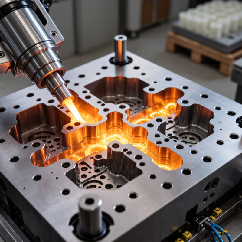
Injection molding tooling turns a part design into a mold that can repeatedly shape molten plastic. The tool usually has two halves: a cavity that forms the part’s outer surface and a core that shapes its interior. Cooling channels, gates, vents, and ejector pins help control filling, cooling, and release.

How Injection Molding Tooling Works Step by Step

The process starts with a reviewed part design. Engineers check wall thickness, draft angles, undercuts, and likely shrinkage. A draft angle helps the cooled part release without scraping the mold. The mold is then machined, assembled, and tested. During a trial, molten resin enters through the gate and fills the cavity under pressure. Cooling channels carry heat away. Once the plastic stiffens, the mold opens and ejector pins push the part free. Measurements and surface checks reveal issues such as warping, short shots, or flash. Adjustments may follow; the first trial is not always clean.

Tips: Ask for a trial report with part measurements and process settings. Watch how the part ejects, not only how it looks. A small change in gate location or cooling can affect cycle time and part quality, so confirm changes with another test.

How Tooling Design Affects Part Quality and Production

Injection molding tooling controls much more than part shape. It governs cooling, filling, ejection, and repeatability. A poorly balanced gate can create weld lines, sink marks, or uneven gloss. In practice, cooling channels deserve special attention. Uneven heat removal often causes warpage after ejection, even when the machine settings look correct. According to Grand View Research’s 2024 injection-molded plastics report, the market is projected to grow at about 4.6% annually through 2030. That growth increases pressure for stable cycle times and fewer rejected parts.

Tooling design also affects production cost. Conformal cooling, Moldflow analysis, and carefully placed vents can shorten cycles and reduce trapped air. However, simulation is not a guarantee. Material batches, humidity, and small machining errors can still change results. The first mold is rarely perfect. That is normal. The critical response is disciplined measurement. Engineers should compare cavity pressure, mold temperature, part weight, and dimensional inspection results. The 2023 Plastics Industry Association industry report highlights continuing demand for efficiency and reliable domestic production, making maintenance and process control increasingly important.

Tips: Specify shrinkage by resin grade, not by habit. Keep vents clean and inspect them regularly. Validate cooling with thermal measurements. Leave access for future repairs. A cheaper mold can become expensive when every cycle repeats the same defect. Conversely, overengineering may add cost without improving the part. Good tooling is a measured compromise, not a polished guess.

Common Tooling Materials, Maintenance, and Applications

Injection molding tooling is the mold system that shapes heated polymer into repeatable parts. Its material choice affects cycle time, wear, heat transfer, and surface quality. Hardened tool steel suits long production runs and abrasive compounds. Pre-hardened steel supports faster machining and moderate volumes. Aluminum offers quick machining and efficient cooling, but it can dent more easily.

According to a 2024 Fortune Business Insights report, the global injection molding machine market reached about USD 19.78 billion in 2023. This scale explains why tooling reliability matters across automotive, medical devices, electronics, packaging, and household products. PlasticsEurope reported 400.3 million tonnes of global plastics production in 2022. Many of these products depend on carefully maintained molds.

Maintenance begins with disciplined cleaning. Technicians should remove resin buildup, inspect vents, and check ejector pins after scheduled cycles. Cooling channels deserve attention. Restricted flow creates uneven shrinkage, visible warpage, and longer cycles. The Plastics Industry Association identifies process efficiency as a major competitiveness factor, yet maintenance is often treated as downtime. That assumption is convenient, but incomplete. A polished cavity can still fail when alignment, temperature control, or venting is ignored. In practice, detailed inspection records help reveal gradual wear before flash or dimensional drift becomes expensive. Some teams still replace components too early. Others wait too long. Neither approach is ideal.

What Is Injection Molding Tooling and How Does It Work? - Common Tooling Materials, Maintenance, and Applications

Category Item or Stage Key Characteristics Typical Application or Function Maintenance Considerations
Tooling Definition Injection mold A precision tool containing one or more cavities that shape molten plastic into a finished part. Used in thermoplastic, thermoset, and some elastomer molding processes. Inspect cavity surfaces, parting lines, cooling circuits, vents, and moving components regularly.
Operating Principle Clamping The mold halves close and are held together under force to resist injection pressure. Prevents flash and maintains dimensional accuracy during filling and packing. Check alignment, guide pins, bushings, clamps, and signs of parting-line wear.
Operating Principle Injection and filling A heated barrel plasticizes the material, and a screw or plunger forces it through the sprue, runners, and gates into the cavity. Creates the basic shape of the molded component. Keep gates and vents free of residue; monitor for short shots, burn marks, and uneven filling.
Operating Principle Packing and cooling Additional pressure compensates for material shrinkage while cooling channels remove heat from the mold. Controls shrinkage, warpage, cycle time, and part stability. Flush and check cooling passages for scale, corrosion, blockages, and inconsistent flow.
Operating Principle Ejection Ejector pins, sleeves, plates, or air assist release the solidified part after mold opening. Enables automated or manual part removal without damaging the component. Lubricate approved moving surfaces, check pin return, and inspect for sticking or uneven ejection.
Tooling Material P20 pre-hardened tool steel Good machinability, moderate strength, and suitable polishability; commonly supplied in a pre-hardened condition. General-purpose molds for medium-volume production and larger mold bases. Protect against corrosion and inspect wear areas, especially when using abrasive or glass-filled plastics.
Tooling Material H13 hot-work tool steel High hot-strength, toughness, and resistance to thermal fatigue. Molds exposed to elevated temperatures, repeated thermal cycling, or demanding production conditions. Monitor heat checking, cracking, and cooling performance; maintain clean and dry mold surfaces.
Tooling Material Stainless mold steel Improved corrosion resistance compared with conventional carbon and low-alloy steels. Molds used with corrosive polymers, moisture-prone environments, medical components, or demanding surface finishes. Clean and dry after production; inspect polished areas and cooling circuits for staining or corrosion.
Tooling Material Aluminum Lightweight, relatively easy to machine, and highly thermally conductive, but generally less wear-resistant than hardened steel. Prototype, bridge, pilot, and lower-volume molds with moderate material and production demands. Use careful cleaning methods; inspect cavity edges, shutoffs, threads, and surfaces for dents or erosion.
Tooling Component Cavity and core The cavity forms the external features, while the core forms internal features and surfaces. Defines the part geometry, surface texture, wall details, and dimensional characteristics. Check for scratches, deposits, corrosion, dimensional wear, and damage to fine features.
Tooling Component Runner and gate system Channels that distribute molten material from the sprue to one or more cavities. Controls filling balance, gate vestige, pressure loss, and material waste. Remove buildup, inspect gate dimensions, and verify that hot-runner components are functioning correctly when applicable.
Tooling Component Venting system Small passages allow trapped air and gases to escape as the cavity fills. Reduces burn marks, incomplete filling, gas traps, and surface defects. Clean vents when deposits accumulate and confirm that vent depth and location remain within design requirements.
Maintenance Routine cleaning Removes resin residue, grease, dust, corrosion products, and molded-part debris. Preserves surface quality, vent performance, and reliable mold closing. Perform after production runs or according to the processor's maintenance schedule; use non-abrasive, compatible cleaners.
Maintenance Lubrication and corrosion protection Reduces friction in moving components and protects exposed metal surfaces during storage. Supports smooth ejection, mold opening, slide movement, and long-term storage. Apply compatible lubricants sparingly to specified areas; remove excess lubricant from cavity and parting surfaces.
Maintenance Dimensional and visual inspection Combines measurement of critical features with checks for wear, cracks, burrs, flash, and surface damage. Detects problems before they cause widespread part defects or unplanned downtime. Record inspection results and compare them with approved mold drawings and part specifications.
Application Automotive and transportation components Often requires dimensional consistency, impact performance, complex geometry, and durable tooling. Interior trim, housings, clips, brackets, bezels, and functional under-hood components. Pay close attention to abrasive fillers, mold wear, cooling balance, and repeatability across cavities.
Application Medical and laboratory products Usually demands cleanable surfaces, tight dimensional control, controlled materials, and traceable processes. Disposable housings, fluid-handling components, diagnostic parts, and laboratory consumables. Use corrosion-resistant tooling where appropriate and document cleaning, inspection, and repair activities.
Application Consumer, electrical, and industrial products Applications range from visible cosmetic parts to durable structural housings and technical components. Appliance parts, electronic enclosures, packaging components, handles, connectors, and machine components. Match steel grade, surface finish, cooling design, and maintenance frequency to production volume and resin abrasiveness.

Note: Tooling material selection, maintenance frequency, service life, and production suitability depend on part geometry, resin type, additives, cycle conditions, required surface finish, and planned production volume.