

Selecting the right Voltage Transformer is not a paperwork exercise. It is a protection, measurement, and safety decision.
The International Energy Agency’s Electricity 2024 report expects global electricity demand to keep rising through 2026. That growth places more pressure on substations, monitoring systems, and dependable voltage measurement. The U.S. Department of Energy also treats transformer efficiency and grid modernization as important planning issues. These reports point to a practical reality: small specification mistakes can become costly field problems.
As transformer author William H. Hayt, Jr. explains, “A transformer is a device that transfers electric energy from one alternating-current circuit to another.” That transfer must remain accurate under real operating conditions. Engineers should examine rated primary voltage, secondary voltage, burden, accuracy class, insulation level, frequency, and installation environment. Seven practical checks can organize that work.
Do not trust the nameplate alone.
A transformer may meet its ratio on paper yet perform poorly with excessive burden, harmonics, heat, or long secondary wiring. Field experience often exposes these gaps. This guide therefore connects data-sheet values with actual substation conditions, including relay inputs, meters, cable length, grounding, and available fault levels. IEC 61869 and IEEE C57.13 provide useful reference points, but neither standard replaces site-specific engineering judgment. Forecasts and catalog claims can also differ. That deserves honest review. The best choice is rarely the cheapest unit; it is the unit that remains accurate, stable, and serviceable throughout its expected duty.
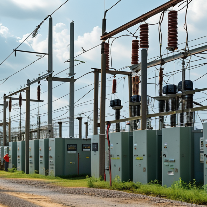
Start by mapping the system, not the transformer label. Confirm whether the source operates at 50 or 60 Hz, then verify the load frequency. A mismatch can increase heating, audible noise, and measurement error. IEC 60038 defines preferred supply voltages and frequency conditions, but local networks may differ. Check the site records.
Phase configuration matters. A single-phase transformer suits many small control panels and laboratory loads. Three-phase equipment needs balanced connections, correct phase rotation, and suitable insulation. The U.S. Department of Energy’s 2022 Distribution Transformer Technical Support Document notes that distribution transformers commonly operate continuously under demanding load conditions. That supports careful thermal and phase evaluation.
Input range deserves equal attention. Record the minimum, nominal, and maximum voltage during real operating hours. A transformer rated only for nominal input may fail during brownouts or switching events. The International Energy Agency’s Electricity 2024 report projects global electricity demand to rise by about 3.4% annually from 2024 through 2026. More connected equipment means less room for vague specifications. Select a model with an appropriate tolerance band, not the widest range automatically. Wide ranges can reduce efficiency or increase cost. I have seen projects overlook startup voltage. That mistake is easy to repeat. Recheck it with a calibrated meter, and compare readings across phases before approval.
Choosing the right voltage transformer starts with its VA capacity, not only its input and output voltage. VA means volt-amperes, and it describes the load the transformer can support. Tip 1: Add the rated VA of every connected device. Tip 2: Include control circuits, lamps, sensors, and small motors. These minor loads are easy to miss.
Tip 3: Keep the continuous load below 80% of the transformer rating. For example, a 1,000 VA transformer should normally carry no more than 800 VA continuously. This reserve reduces heat and leaves room for load changes. Tip 4: Check startup demand. A motor may draw several times its running current for a few seconds. My early estimates were too optimistic because I measured only steady operation. That mistake caused nuisance voltage drops.
Tip 5: Consider power factor, especially with motors, coils, or switching supplies. Their current may exceed a simple watt calculation. Tip 6: Review the installation environment. High ambient temperature, limited ventilation, and dust can reduce practical capacity. Tip 7: Confirm the primary and secondary voltage, frequency, phase, and required connection method before ordering. A calculation sheet helps, but it should match actual field measurements. Leave extra capacity when future equipment is likely. Bigger is not always better, though; an oversized transformer can be less efficient and cost more. Check the details twice.
For reliable continuous operation, keep the expected load at or below 80% of the transformer’s rated VA capacity. For example, a 2,000 VA transformer should normally supply no more than 1,600 VA continuously, leaving capacity for heat, startup current, and load variation.
Choosing a voltage transformer starts with the load, not the nameplate. Regulation measures voltage change between no-load and rated-load conditions. Accuracy measures how closely the transformed voltage matches the true value. They are related, but they are not interchangeable.
IEC 61869-3 and IEEE C57.13 identify common measurement classes, including 0.5, 1.0, and 3.0. A Class 0.5 transformer allows approximately 0.5% ratio error under specified voltage, frequency, and burden conditions. Class 1.0 permits about 1%, while Class 3.0 permits about 3%. That difference matters.
A 10,000-volt primary can produce an error of roughly 50 volts at Class 0.5, but about 300 volts at Class 3.0. Metering, calibration, and power-quality studies usually justify tighter accuracy.
Check regulation across the real operating range. A transformer may meet its accuracy class at rated burden, then drift when long cables, meters, or relays add impedance. The U.S. Department of Energy’s transformer efficiency guidance also emphasizes evaluating performance under actual loading, rather than relying only on rated values.
I have seen selection sheets focus heavily on accuracy while overlooking cable burden. That is an expensive blind spot.
For routine indication, Class 3.0 may be adequate. For billing-grade measurement or laboratory testing, Class 0.5 is safer. Class 1.0 often offers a practical compromise, but only after comparing phase error, burden, temperature, and expected voltage variation.
Tip 1: Check efficiency at the rated load, not at idle. A practical target is at least 95% efficiency under normal operating conditions. The U.S. Department of Energy’s distribution-transformer standards evaluate both no-load and load losses. This distinction matters because a transformer can look efficient during light testing but waste more energy near capacity. Request a test report based on recognized IEC or IEEE procedures. Ask for efficiency at 25%, 50%, 75%, and 100% load.
Tip 2: Treat heat as a performance signal. Every lost watt becomes heat inside the enclosure. The International Energy Agency reports that global electricity networks lose roughly 8% of generated electricity during transmission and distribution. Transformer losses are only one part, but they remain important in dense facilities. Check temperature-rise data, cooling design, ventilation, and ambient-temperature limits. A unit operating beside a hot ceiling may perform differently from the laboratory result. That detail is easy to miss.
Tip 3: Compare efficiency with real operating patterns. A lightly loaded transformer may benefit from low no-load losses, while a factory transformer needs strong full-load performance. Calculate annual energy use from expected load hours, not the nameplate alone. I have seen selection decisions favor a lower purchase price, then overlook continuous heat and energy costs. That choice may be reasonable in some installations, but it deserves a documented calculation. Review efficiency tolerance, measurement uncertainty, and thermal margins before approval.
| Tip | Key Selection Dimension | Typical Requirement or Target | Why It Matters | Example Evaluation | Selection Guidance |
|---|---|---|---|---|---|
| 1 | Input and output voltage | Match the transformer to the system's nominal voltage, frequency, and required output voltage. Allow for the specified input-voltage tolerance. | An incorrect voltage ratio can cause overvoltage, undervoltage, insulation stress, or malfunction of connected equipment. | For a 400 V, 50 Hz supply requiring 230 V, select a transformer with a rated ratio close to 400:230 and verify the permitted input range. | Confirm primary voltage, secondary voltage, frequency, phase configuration, and any available tap settings before comparing efficiency. |
| 2 | Rated power and load capacity | Choose a rating above the expected continuous load. A practical design margin is often 20–30%, subject to the load profile and applicable standards. | Operating continuously at or above the rating increases temperature rise and may shorten insulation life. | A calculated 800 VA load may justify a transformer rated around 1,000 VA, provided the inrush current and duty cycle are acceptable. | Calculate real power, apparent power, power factor, motor starting current, and future expansion requirements. |
| 3 | Efficiency at rated load | Target ≥95% efficiency at rated load for general-purpose units; compare the manufacturer's test conditions and efficiency curve. | Higher efficiency reduces wasted energy, operating cost, and internal heat generation. | A 2,000 VA transformer operating at 95% efficiency loses approximately 100 VA as heat at rated load. At 98% efficiency, the loss is approximately 40 VA. | Do not compare percentages without checking whether the figures apply at the same load, voltage, frequency, temperature, and power factor. |
| 4 | Heat dissipation and temperature rise | Prefer a documented temperature-rise value suitable for the enclosure and ambient conditions. Lower temperature rise is generally beneficial. | Every watt of transformer loss becomes heat. Excessive heat can reduce reliability and accelerate insulation aging. | A unit with 150 W of total loss requires substantially more ventilation than one with 60 W of loss at the same output rating. | Check maximum ambient temperature, cooling method, enclosure ventilation, clearance, and the stated temperature-rise limit. |
| 5 | No-load and part-load performance | Review no-load loss and efficiency at the actual operating range, especially when the load is intermittent or normally below 50%. | A transformer can meet a high rated-load efficiency target yet waste significant energy while energized with little or no load. | For a control panel that is energized continuously but normally uses 20–40% of capacity, part-load loss may matter more than full-load efficiency. | Request no-load loss, full-load loss, and an efficiency curve or test data covering the expected duty cycle. |
| 6 | Inrush current and voltage regulation | Verify energization inrush and secondary voltage regulation against the upstream protective device and the connected load. | High inrush can nuisance-trip breakers or fuses, while poor regulation can reduce the output voltage under load. | Motors, relays, contactors, capacitive-input power supplies, and control circuits may require additional capacity during startup. | Check inrush-current data, recommended overcurrent protection, impedance, and full-load secondary voltage. |
| 7 | Safety, insulation, and installation environment | Use insulation and protection ratings appropriate for the application, including dielectric strength, enclosure rating, grounding, and overcurrent protection. | Correct electrical and environmental protection reduces shock, fire, moisture, dust, and insulation-failure risks. | Indoor clean locations may need a different enclosure and cooling arrangement than outdoor, dusty, humid, or corrosive environments. | Verify applicable local requirements, clearance and creepage distances, mounting orientation, ambient temperature, altitude, and maintenance access. |
Note: Efficiency and temperature values should be verified from standardized test data for the exact transformer configuration. Actual performance depends on load, power factor, frequency, ambient temperature, installation, and cooling conditions.
Safety validation should come before price, size, or delivery time. Check whether the design meets IEC 61558 requirements for transformers, separation, and insulation coordination. For North American applications, verify UL 506 suitability and the exact construction category. Do not accept a generic certificate. Request test reports, rated voltage, frequency, temperature rise, and abnormal-condition results. One certificate may cover one model, not every variant.
Inspect insulation as a complete system. Confirm working voltage, dielectric withstand, creepage, clearance, and insulation class. Ask whether barriers and bobbin materials match the pollution degree. Small gaps matter.
The U.S. Bureau of Labor Statistics recorded 145 fatal occupational injuries involving electric current in 2022. Its Census of Fatal Occupational Injuries data supports a practical lesson: enclosure details and installation controls deserve equal attention.
Measure supply voltage, load, inrush current, and ambient temperature. I have seen selections fail because “230 V” was treated as a complete specification.
Use IP ratings according to IEC 60529. IP54 limits dust entry and resists splashing, but it is not waterproof. Check cable glands, door seals, drain paths, and mounting orientation.
Review fault protection, earthing, touch-safe terminals, and accessible temperature. Independent laboratory evidence is stronger than marketing language.
Still, field conditions are messy. Condensation and loose connections can defeat a correct rating. Record every check and arrange a qualified review after installation.

