

Choosing the right lens for industrial inspection is rarely a simple shopping decision. A telecentric macro lens must match the camera, sensor, working distance, lighting, and measurement tolerance. A lens that performs beautifully on a laboratory bench may struggle beside a fast production line.
This guide examines leading telecentric macro lenses for inspection applications. It focuses on practical details, including magnification stability, distortion control, depth of field, image contrast, and compatibility with common machine vision systems. These factors affect whether an operator can measure a tiny connector pin, molded edge, or machined hole with confidence.
Precision matters.
True telecentricity helps reduce apparent size changes when parts shift slightly along the optical axis. That advantage is valuable when fixtures cannot hold every component perfectly. However, telecentric performance is not magic. Lighting quality, sensor resolution, vibration, and calibration still influence the final result.
The comparison also considers working distance and field coverage. A narrow field may reveal fine surface defects but slow inspection throughput. A wider field can capture more features, though it may reduce detail. Some models offer excellent optical correction but require larger, carefully aligned illumination systems.
There is no universally best lens. That is worth remembering. The most expensive option may not deliver the best value for a specific inspection task. Specifications can also appear impressive while hiding practical limitations, such as difficult mounting or limited availability.
By examining strengths, trade-offs, and suitable use cases, this overview helps engineers create a more reliable shortlist. The final choice should come from test images, dimensional trials, and real production conditions—not from catalog numbers alone.
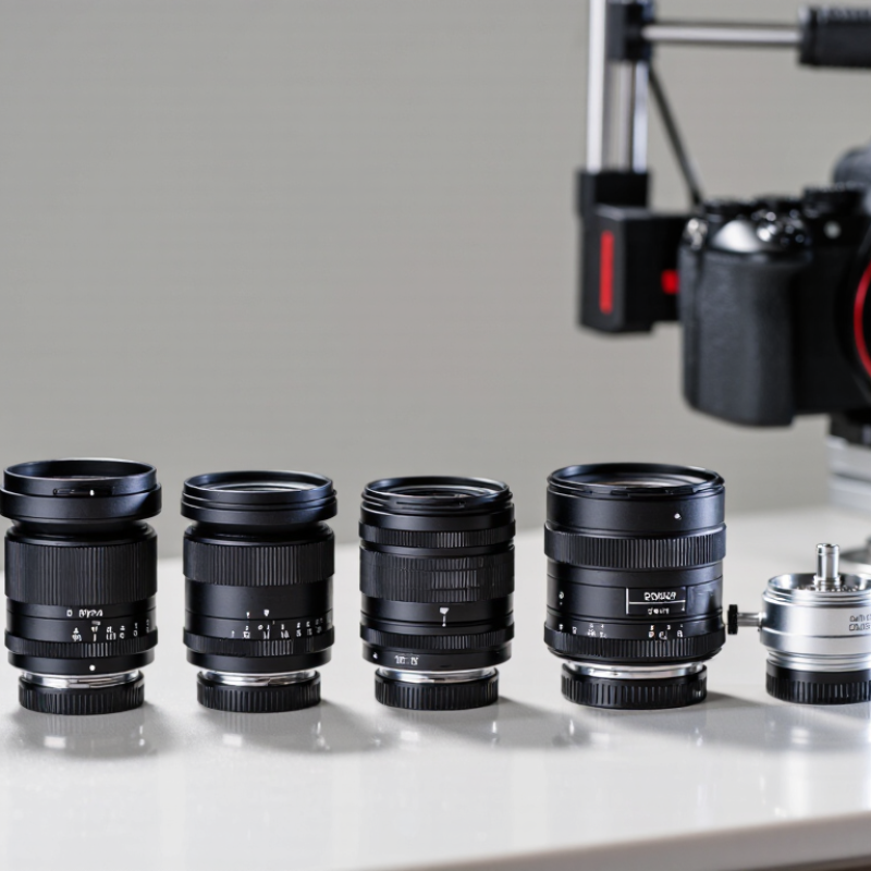
What Are the Top Telecentric Macro Lenses for Inspection?
What Defines a Telecentric Macro Lens for Inspection?
A telecentric macro lens keeps chief rays nearly parallel to the optical axis. This geometry reduces perspective error. A hole near the image edge should appear nearly the same size as one at the center. That matters when measuring pins, molded parts, wafers, or machined edges. Object-space telecentricity is usually preferred for dimensional inspection. Bilateral telecentric designs control magnification on both sides.
The best lens is not simply the one with the highest magnification. Check telecentricity, distortion, working distance, numerical aperture, and usable image circle. A distortion figure below 0.1% can support precise measurement, but the camera, lighting, and calibration still affect final accuracy. Resolution must match the smallest feature. A 2024 North American machine-vision statistics report valued annual vision-system sales at roughly 3.4 billion dollars, showing the scale of industrial inspection demand. More automation also exposes weak optical choices.
In practice, a long working distance helps protect the lens from dust and moving parts. Coaxial lighting can reveal flat surfaces, while dark-field lighting exposes scratches and raised edges. Stop down carefully. Excessive aperture reduction may improve depth of field but increase diffraction. The uncomfortable detail is that telecentricity does not remove every measurement error. Temperature, lens mounting, vibration, and imperfect calibration still matter. A controlled test with certified artifacts is more reliable than a catalog promise. Some specifications also depend on the chosen sensor, which is easy to overlook.
Telecentric macro lenses are designed to keep magnification nearly constant as the object moves within the usable depth range. Their defining characteristics are near-zero chief-ray angle, minimized perspective error, and stable dimensional measurement.
The chart uses a normalized inspection benchmark: lower values are better for perspective and magnification sensitivity, while higher values are better for measurement stability. The values represent optical design principles rather than a ranking of manufacturers or products.
Telecentric macro lenses improve measurement accuracy by keeping magnification stable across depth. A conventional lens makes a near edge appear larger than a distant edge. That perspective error can distort hole diameters, pin positions, and component widths. Telecentric optics reduce this effect, so the measured outline stays closer to its actual size. In practice, this matters when a part moves slightly inside the inspection area.
Lens selection should begin with the measurement task, not the highest specification. Object-space telecentric designs are useful for flat parts and dimensional checks. Bi-telecentric designs can improve stability when both object and sensor alignment matter. Low distortion is essential. A lens with 0.1% distortion can create a 10-micrometre error across a 10-millimetre feature. Calibration still matters. Even excellent optics cannot correct poor lighting, vibration, or an unstable fixture.
Industry demand supports this focus. Grand View Research valued the global machine vision market at about USD 13.2 billion in 2023 and projects strong growth through 2030. MarketsandMarkets also identifies inspection and quality control as major machine vision applications in its 2024 market analysis. These figures show expanding adoption, but they do not guarantee better measurements. Engineers should verify repeatability with certified gauges and ISO 10360-style testing principles. A wider field of view may reduce resolution. A longer working distance may lower numerical aperture. That trade-off is easy to overlook. Calibration can also expose uncomfortable errors in the lens, lighting, or fixture.
What Are the Top Telecentric Macro Lenses for Inspection?
Key Specifications for Comparing Inspection Lenses
A top inspection lens starts with measurement stability, not maximum magnification. Check telecentricity across the full object field. A practical target is below 0.1% magnification change when object distance shifts. This matters when a metal edge moves several millimeters. Record working distance, field of view, and sensor coverage together. A lens that fits the sensor poorly can create dark corners and wasted pixels.
Resolution needs a measurable reference. ISO 12233:2017 provides methods for evaluating spatial resolution, while EMVA 1288 Release 4.0 defines image-quality measurements such as signal-to-noise ratio and dynamic range. Compare MTF at the camera’s Nyquist frequency, not only the lens’s advertised line pairs. Small details disappear there. Distortion should also remain low, often below 0.1% for precision gauging. These figures are targets, not universal rules.
Lighting changes the decision. High numerical aperture can improve resolution, but it usually reduces depth of field. A 2024 International Federation of Robotics report recorded 541,000 industrial robot installations worldwide in 2023, increasing demand for reliable inline inspection. That pressure can expose weak lens choices quickly. I still treat depth of field as a compromise. A lens may resolve a 20-micron feature, yet fail when the part tilts slightly. Test repeatability with real parts, vibration, reflective surfaces, and the final working distance. Use measured data, not a catalog promise.
Telecentric macro lenses are chosen by inspection task, not by magnification alone. Their parallel chief rays help maintain stable object size when parts move slightly along the optical axis. This matters during dimensional inspection, where a small measurement shift can reject a usable component.
For flat metal plates, glass panels, and machined surfaces, a bilateral telecentric lens provides consistent scale across the field of view. Pair it with diffuse, even lighting to reveal edges without harsh reflections. PCB inspection often needs moderate magnification, generous working distance, and enough depth of field for connectors and soldered components. A narrow field may show fine detail, but it can slow production.
Molded plastic parts and medical components can require higher magnification and strong edge contrast. A lens with low distortion is valuable when software compares circular holes or molded profiles. Cylindrical parts need careful lighting and may benefit from a coaxial or backlight arrangement. Do not overlook sensor size. An apparently suitable lens may crop the image or waste resolution. Working distance also affects access for clamps, air lines, and moving stages.
In practice, lens selection is rarely perfect on the first attempt. I have seen excellent optics underperform because the light source was poorly matched. Test the complete system with real parts, temperature changes, and expected positioning errors. That evidence is more reliable than a specification sheet alone.
Selecting a telecentric macro lens starts with the inspection task, not the lens catalogue. Define the object field, sensor size, working distance, and required pixel resolution. Telecentric imaging keeps magnification more stable when part height changes. That matters when measuring edges, holes, or molded surfaces.
Automation demand is increasing. The International Federation of Robotics reported 541,302 industrial robots installed worldwide in 2023. MarketsandMarkets’ 2024 Machine Vision Market report projects growth from about USD 13.7 billion in 2023 to USD 21.4 billion by 2028. These figures support careful optical planning, rather than automatic equipment upgrades. A larger sensor needs an image circle that fully covers it. A short working distance may simplify the enclosure, but it can restrict lighting and maintenance access.
Check distortion, telecentricity error, numerical aperture, and depth of field together. Resolution on a specification sheet can look impressive. It may fail under low-contrast lighting. Match the lens to coaxial, dome, or backlighting conditions before finalizing the camera. Use a calibrated target at the real working distance. Measure repeatability across several object heights. Test it twice.
I would also leave tolerance for dust, thermal drift, and imperfect alignment. A lens that performs perfectly on a clean chart may produce unstable measurements on a production line. The best choice is the lens that preserves accuracy after vibration, lighting changes, and routine operator handling.
| Lens Configuration | Typical Magnification | Working Distance | Maximum Sensor Format | Typical Distortion | Telecentricity | Typical Resolution | Recommended Inspection Use | Key Selection Consideration |
|---|---|---|---|---|---|---|---|---|
| Low-Magnification Telecentric Macro Lens | 0.25×–0.50× | 100–200 mm | 2/3 in to 1.1 in | <0.10% | Object-space telecentric | Approximately 20–40 line pairs/mm, depending on sensor and illumination | Large components, connector housings, molded plastic parts, and dimensional checks | Choose when the field of view must be wide while maintaining stable apparent size across depth. |
| Medium-Magnification Telecentric Macro Lens | 0.50×–1.00× | 65–110 mm | 2/3 in to 1.1 in | <0.05% | Object-space telecentric | Approximately 30–60 line pairs/mm, depending on aperture and sensor pixel size | Precision gauging, hole measurement, edge location, and assembly verification | A strong general-purpose choice when measurement repeatability is more important than a long working distance. |
| High-Magnification Telecentric Macro Lens | 1.00×–2.00× | 35–65 mm | 1/2 in to 2/3 in | <0.05% | Object-space telecentric | Approximately 40–80 line pairs/mm under controlled lighting | Small machined features, micro-connectors, electronic components, and fine surface defects | Use when the inspection feature is small and the camera has sufficient pixel resolution for the required tolerance. |
| Long-Working-Distance Telecentric Lens | 0.30×–0.75× | 150–300 mm | 2/3 in to 1.1 in | <0.10% | Object-space telecentric | Approximately 20–50 line pairs/mm | Deep cavities, hot parts, moving production lines, and applications requiring mechanical clearance | Prefer this configuration when lighting, robot access, part handling, or operator safety requires additional space around the object. |
| Large-Format Telecentric Macro Lens | 0.20×–0.50× | 100–250 mm | 1.1 in to 4/3 in | <0.15% | Object-space telecentric | Approximately 20–45 line pairs/mm | Large flat parts, display components, wafers, trays, and multi-feature inspection in one image | Confirm that the lens image circle fully covers the sensor; undersizing the image circle can cause vignetting and measurement errors. |
| Bi-Telecentric Measurement Lens | 0.50×–1.00× | 80–150 mm | 2/3 in to 1.1 in | <0.02% | Object-space and image-space telecentric | Approximately 30–60 line pairs/mm | High-accuracy dimensional metrology, calibrated gauging, and parts with significant height variation | Select when changes in object distance and image-space geometry must have minimal influence on measured size. |
| Coaxial-Illumination Telecentric Lens | 0.25×–1.00× | 65–150 mm | 2/3 in to 1.1 in | <0.10% | Object-space telecentric | Approximately 25–60 line pairs/mm | Reflective surfaces, printed markings, polished metal, glass, and flatness inspection | Use when uniform on-axis illumination is needed; verify that the integrated light path does not reduce available aperture. |

