How Does the Injection Moulding Process Work?
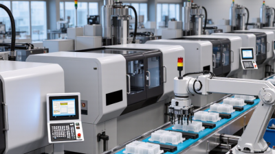
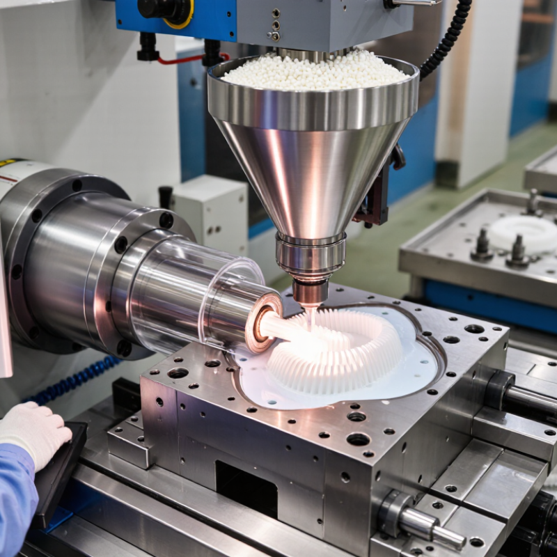
Injection moulding turns plastic pellets into repeatable parts through heat, pressure, and a shaped mould. The injection moulding process begins when pellets enter a machine hopper and travel into a heated barrel. A rotating screw moves them forward, mixing and melting the material. The result should be a consistent melt, though material choice and machine settings affect how it behaves.
The mould closes under clamping force. Then the screw pushes molten plastic through a nozzle and into the mould cavity. It sounds simple. In practice, filling every section evenly takes careful control. The plastic cools and hardens against the mould’s surfaces, forming details such as ribs, edges, and small mounting points. Once the part is firm enough, the mould opens and ejector pins release it. That detail matters.
Operators monitor temperatures, injection speed, pressure, cooling time, and part appearance. A sink mark, short fill, or warped edge can signal that settings, mould design, or material conditions need attention. The exact cycle varies by polymer, component geometry, and equipment, so one recipe rarely suits every job. A clear overview helps readers understand each stage, but it cannot replace trials and measurements on a real production line. Even a stable process needs review when materials or design requirements change. That is an easy point to overlook.
Preparing the Plastic Material and Injection Mould
Before the machine runs, the resin must be prepared for a predictable melt. Pellets are checked for contamination and dried when the material specification requires it. Moisture can create bubbles, streaks, or weak spots in the finished part. Drying temperature and time should follow the material supplier’s technical data, not guesswork. Small details matter. After drying, pellets move into a clean hopper, where colorants or additives are measured carefully. An uneven blend may show up as pale swirls or inconsistent strength. Excessive heat can degrade some resins, so barrel settings need controlled checks. Drying is easy to rush. Shop conditions also change; humidity and pellet storage can undo careful preparation.
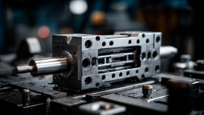
Meanwhile, the mould is inspected before it is mounted and clamped. Technicians clean the cavity and core, then check vents, gates, and cooling channels for blockages. Even a thin film of residue can mark the surface or affect release. Alignment matters too: mismatched halves may cause flash along the parting line. Cooling lines should be tested for flow, and the mould brought into its specified temperature range. A short trial shot can reveal trapped air, poor filling, or an unexpected surface mark. Not every defect has one cause. Material moisture, mould temperature, and venting can interact, so adjustments are best made one variable at a time.
Melting the Material and Injecting It into the Mould
Injection moulding begins when measured plastic pellets enter a heated barrel. A rotating screw carries them forward as heater bands soften and melt the material. The screw also mixes the melt, helping reduce temperature and colour variations. It is not instant. Melting depends on the resin, machine settings, screw design, and pellet moisture. Excessive heat can degrade some plastics, so operators monitor melt condition instead of relying on one display.
When enough melt gathers ahead of the screw, injection begins. The screw advances like a plunger, pushing material through the nozzle, runner, and gate into the closed mould. The melt fills narrow ribs and corners, then pressure holds it in place as it cools and shrinks. It varies. Poorly matched speed or pressure can cause short shots, flash, or burn marks. Mould temperature and venting also affect the result. A technician may inspect a fresh part, check its weight and surface, then adjust one setting at a time. This can feel slow, but changing several settings together makes cause and effect harder to see.
Cooling the Part and Solidifying Its Shape
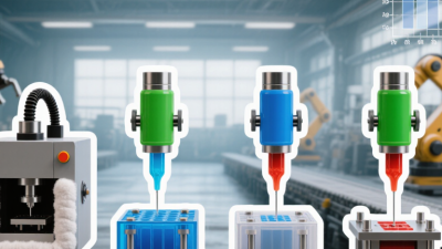
Once the mould is filled, cooling begins while the plastic remains under pressure. Heat moves from the part into the steel mould, then through cooling channels carrying temperature-controlled water or another fluid. The goal is not simply to make the part cold. It is to cool it evenly enough to preserve its intended shape.
Thick sections hold heat longer than thin walls. A plastic rib beside a thin panel can therefore shrink at a different rate, causing sink marks or slight warping. Cooling-channel layout, mould temperature, material, and part thickness all affect the time required. Not instantly. Operators often check the part’s temperature and stiffness before adjusting the cycle, since early ejection can leave a mark or let a wall bend. But extending cooling time without a clear reason can slow production and may not fix uneven cooling. A clean calculation can still miss a stubborn hot spot; real moulding sometimes needs careful testing. Once the part is stable enough, the mould opens and ejector pins release it. That moment matters: the plastic must hold its shape without being so brittle that ejection damages an edge.
How Does the Injection Moulding Process Work?
Cooling the part allows the molten plastic to solidify and retain its shape.
Estimated cooling time by wall thickness: In idealized, conduction-limited cooling, time rises approximately with the square of the wall thickness. These illustrative estimates use a fixed set of conditions; actual cooling time varies with resin, mould temperature, part geometry, and cooling-channel design.
Opening the Mould and Ejecting the Finished Part
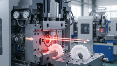
Once the molten polymer has cooled enough to hold its shape, the machine releases its clamping force. The moving platen draws back, separating the two mould halves along the parting line. Slowly, at first. This controlled opening helps prevent a thin wall or delicate edge from catching on the cavity. Sensors and machine settings limit travel and confirm that the mould is fully open before ejection begins. Cooling time matters: eject too early, and a warm part may bend or retain marks. Wait too long, and the cycle becomes less efficient.
At full opening, ejector pins, sleeves, or a stripper plate push the part from the core. Their contact points are planned around the component’s geometry, spreading force instead of concentrating it in one small area. A brief, even push is usually better than a hard strike. The part may drop into a collection bin or be removed by an automated take-out device. Operators check for sticking, drag marks, and incomplete release; these clues can point to draft, cooling, or surface issues. The mechanism sounds straightforward, but it is not perfectly forgiving. A pin can leave a witness mark, and an adjustment that improves release may affect appearance. That trade-off calls for inspecting actual parts, not relying on guesswork.
How Does the Injection Moulding Process Work? - Opening the Mould and Ejecting the Finished Part
This table outlines the typical sequence after the moulded material has cooled sufficiently for ejection. Exact settings and timing depend on the resin, part geometry, mould design, and machine.
| Step |
Machine or Mould Action |
What Happens |
Key Control or Check |
Typical Outcome |
| 1 |
Cooling phase completes |
The part and runner cool inside the closed mould until they are sufficiently rigid to retain their shape during ejection. |
Cooling time, mould temperature, and part condition are monitored. Cooling time is set for the material and part design. |
The moulded part is stable enough to be released without excessive distortion or damage. |
| 2 |
Injection unit withdraws, if required |
On machines where the process requires it, the injection unit moves away from the mould before opening. |
Machine sequence and nozzle clearance are checked to prevent interference during mould movement. |
The nozzle is clear of the mould as the opening movement begins. |
| 3 |
Clamping force is released and the mould opens |
The moving platen separates from the stationary platen. The mould opens along its designed parting line, usually leaving the part on the core side. |
Opening position, speed, and force are set to suit the mould. Safety interlocks prevent access while the machine is operating. |
The mould reaches the programmed open position with enough clearance for ejection and part removal. |
| 4 |
Ejector system advances |
Ejector pins, sleeves, a stripper plate, or another mould-specific mechanism applies force to release the part from the core. |
Ejector stroke and timing are matched to the part and mould. Ejection should be even enough to avoid bending, marks, or cracking. |
The part and, where applicable, the runner are released from the mould surface. |
| 5 |
Part is removed or collected |
The part may fall into a collection area or be removed by an operator or an automated take-out system. |
Check that the part has cleared the mould and that no component remains in the cavity or obstructs the next cycle. |
A moulded part is available for inspection or downstream handling. |
| 6 |
Ejectors retract and the mould closes |
The ejector system returns to its home position, and the moving platen closes the mould for the next cycle. |
Confirm ejector return, mould-area clearance, and correct closing sequence before clamping resumes. |
The mould is closed and ready for the next injection cycle. |
Process note: Ejector marks, sticking, part deformation, or incomplete release can indicate that cooling, draft, surface finish, ejection layout, or process settings need review.